
Cue construction · 3 min read
Pool Cue Anatomy: A Labelled Parts and Compatibility Guide
Cue anatomy describes locations; compatibility requires evidence. A visible collar cannot identify a pin, a dark shaft cannot reveal its internal construction, and matching nominal diameter does not establish fit. Use the PART–EVIDENCE–FIT–HANDOFF worksheet to name what is visible, keep unknowns explicit and transfer seven physical fields to the seller or technician.
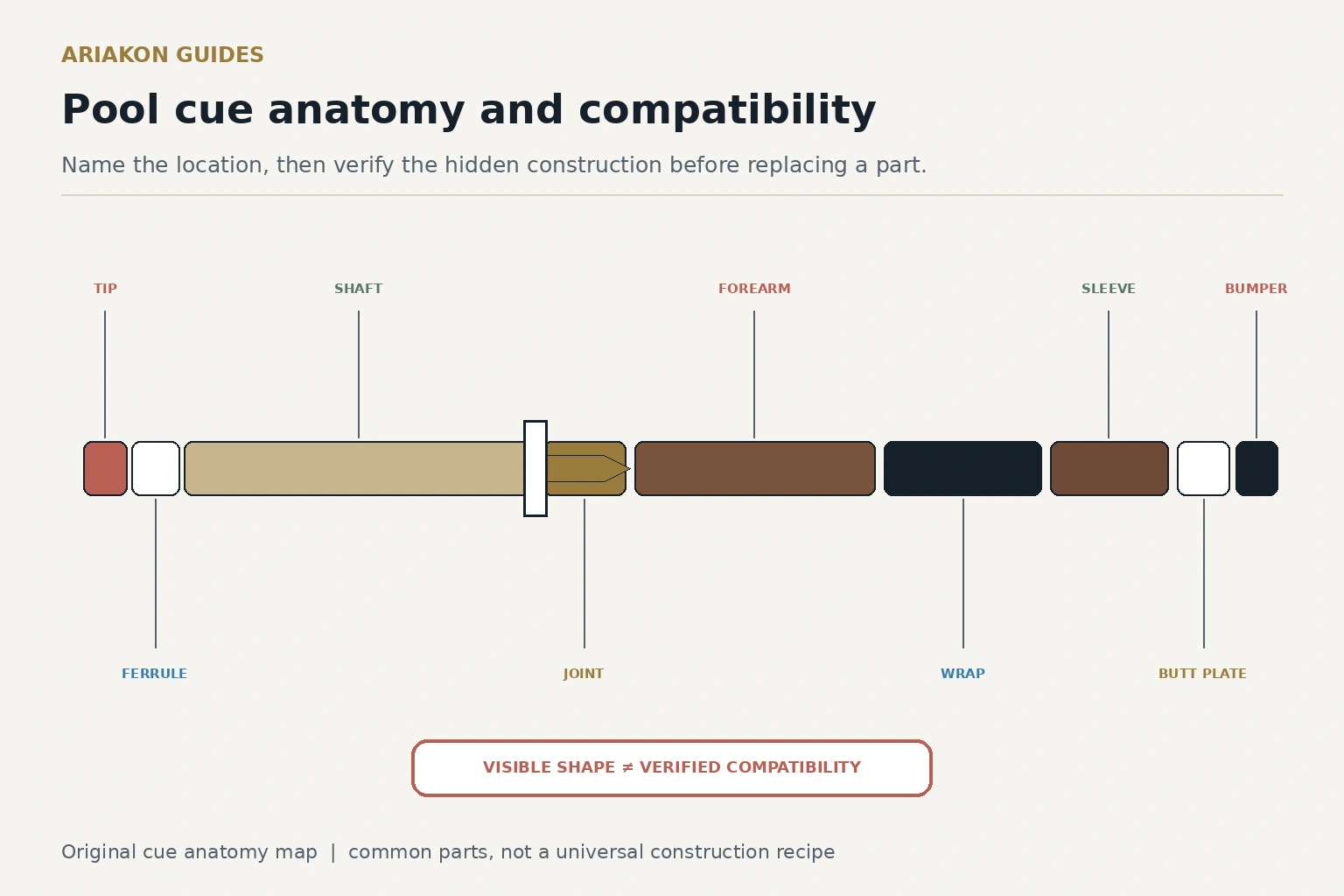
Map common parts from tip to bumper
This is a location map, not a universal construction recipe. Do not disassemble a cue to satisfy curiosity. Exact model documents and qualified inspection outrank visual inference.
| Zone | Common parts | Job | May be absent or hidden |
|---|---|---|---|
| Front end | tip, optional pad, ferrule or ferrule-less transition | contact and front-end protection | pad, core or separate ferrule |
| Shaft | playing surface, taper, collar and joint face | guide through bridge and carry tip | lamination, bore or internal core |
| Joint | pin, threads, pilot, insert, faces and collars | connect shaft and butt on one axis | insert, pilot and thread geometry |
| Butt front | forearm, rings and decorative elements | primary structure and design | core and splice construction |
| Grip | wrap, wrapless handle or coating | grip-hand interface | substrate and adhesive |
| Butt rear | sleeve, butt plate, bumper and possible weight access | rear protection and balance system | weight system or threaded receiver |
Follow the stage-by-stage construction guide for how selected components can become a finished cue.
Map material roles without inferring performance when the question is species and structural role.
Separate visible facts from hidden questions
| Visible fact | Safe record | Do not infer |
|---|---|---|
| Tip layers and approximate diameter | photo and measured diameter | hardness, maker or adhesive |
| Shaft color and taper | surface appearance and measured length | material system or internal construction |
| Joint faces and exposed pin | orthogonal photos without gauges | thread identity from appearance alone |
| Wrap texture | coverage and condition | underlying handle construction |
| Bumper shape | external dimensions and photo | thread or weight access |
| Rings and inlays | location and condition | structural material or cue identity |
Complete seven fit fields before ordering
Send the complete record to the maker, seller or qualified technician and ask for written compatibility with the exact butt. Similar collars and a thread that begins to engage are not evidence. Never force a test fit.
| Field | Record | Evidence |
|---|---|---|
| 1. Maker/model identity | ___ | receipt, label or supported record |
| 2. Joint family | ___ / unknown | exact model document or qualified identification |
| 3. Pin and thread | ___ / unknown | documented specification; no forced gauge |
| 4. Pilot and insert | piloted / flat; insert ___ | clear face photos and documentation |
| 5. Joint-face diameter | ___ mm | suitable caliper without squeezing |
| 6. Collar geometry | material, rings, diameter ___ | orthogonal photo and measurement |
| 7. Length and service constraints | ___ | seller/technician confirmation |
Use the detailed joint-identification worksheet before a replacement-shaft purchase.
Use anatomy to choose the correct service path
| Observation | Stop action | Handoff record |
|---|---|---|
| Loose tip or opening bond | stop play | front-end photos, tip height and model |
| Cracked ferrule or lifted fiber | stop play | location, sound and incident history |
| Joint binds, rocks or leaves a gap | back off without force | both faces, start angle and exact parts |
| Rattle near bumper | do not improvise hidden hardware | model, orientation and when sound occurs |
| Changing ring or inlay gap | document; avoid flex test | dated photographs and storage conditions |
Worked compatibility example
A player records a metal pin, dark collars and a 12.5 mm shaft. The seven-field card still has unknown joint family, thread, pilot and face diameter. The correct result is “not order-ready.” Clear face photographs and the model record go to the prospective seller or technician; the existing parts are never forced together to create an answer.
Inspect a fitted replacement shaft only after documented compatibility and professional fitting.
Keep anatomy distinct from manufacturing
This guide labels parts and prepares a compatibility handoff. The manufacturing guide explains stages and construction choices; the joint guide identifies mating geometry; the ferrule guide covers front-end purpose and repair limits. Those resources remain separate because a location label cannot answer their reader questions.