
Cue buying · 4 min read
Check Piloted Cue-Joint Clearance Before Ordering a Shaft
A replacement shaft can have a familiar thread label and still stop short of the intended mating faces. A projecting locating feature may meet a recess that is too shallow, too narrow or designed for a different contact condition. Use this guide to ask precise clearance questions before ordering. A numerical gap is evidence about one dimension, not proof that the complete joint fits.
Distinguish the locating feature from the fastener
The pin and receiving thread secure the ordinary detachable joint. A pilot is a projecting locating feature around or near that fastening system, paired with a recess. The broad mating faces, outer collars and internal thread geometry are additional interfaces. Different designs can locate or contact differently; not every protrusion is a pilot and not every pilot is intended to float freely.
First identify the exact cue and intended replacement pair. Ask for a drawing or written compatibility confirmation tied to those identities. Do not use a brand-wide rule, visual resemblance or a thread family as a substitute. This guide is narrower than general joint identification and does not describe a particular manufacturer’s construction.
Establish an unknown cue’s identity when the original assembly records are missing.
Record the complete joint identity before comparing a pilot and recess.
Request four geometric fields and the intended contact condition
Use the same reference faces and units in each drawing. The following arithmetic assumes straight cylindrical features and intended clearance; it does not cover a taper, step, elastic fit or required interference. Ask the maker or qualified technician to resolve those cases.
Do not insert a tool into an unfamiliar recess or scratch a finished face to obtain a number. Owner records and a suitable technician’s inspection are preferable to improvised internal measurement. Protect exposed threads while photographing the normal detachable parts.
| Field | Ask for | Boundary |
|---|---|---|
| Axial projection p | Distance from the intended mating face to the pilot end, with tolerance | Do not confuse it with exposed pin length |
| Recess depth d | Usable depth from the receiving mating face, with tolerance | A chamfer or internal obstruction can reduce usable space |
| Pilot diameter P | The locating diameter, with tolerance and shape | A tapered or stepped feature needs more than one diameter |
| Recess diameter D | Mating locating diameter, with tolerance and shape | Entrance size alone may not describe the full recess |
| Contact design | Which surfaces should seat, locate or remain clear? | Positive clearance is not correct for every design |
| Complete pair | Exact thread form, collar transition and assembly instructions | Four dimensions cannot prove complete compatibility |
Work axial clearance as an interval
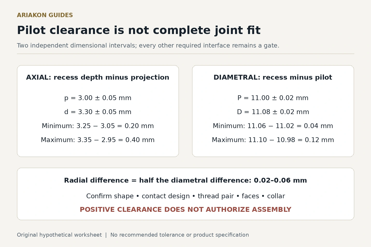
Hypothetical drawings specify p=3.00±0.05 mm and d=3.30±0.05 mm. The nominal difference is 0.30 mm. The smallest difference is 3.25−3.05=0.20 mm; the largest is 3.35−2.95=0.40 mm. This is a worst-case dimensional interval under the stated model, not a statistical probability or measurement result.
If a different recess drawing specified d=3.00±0.05 mm with the same projection, the interval would be −0.10 to +0.10 mm. Zero or a negative difference prevents a simple claim that the pilot end stays clear. It is not permission to shorten the pilot: ask which contact is intended and whether the pair is approved.
Keep diametral and radial clearance separate
In a second hypothetical calculation, P=11.00±0.02 mm and D=11.08±0.02 mm. Minimum diametral clearance is 11.06−11.02=0.04 mm; maximum is 11.10−10.98=0.12 mm. The corresponding radial differences are half as large: 0.02–0.06 mm. Label the column before discussing a gap.
Neither interval proves concentricity, surface condition, thread fit or face contact. A positive diameter difference can coexist with a bad thread, a crooked insert or the wrong axial geometry. These example values are not Ariakon product specifications, recommended tolerances or a machining allowance.
Send a complete ordering question
A hypothetical packet can have four dimensional entries but no written thread-pair confirmation. Its result is hold, not four out of six means mostly compatible. Resolve every required interface before purchase. Save the dated reply and actual seller terms; this guide promises no coverage, refund, inventory or fit service.
On receipt, stop for binding, a premature hard stop, a face gap or damage. Never sand, tap or force the assembly to see whether it can be made to fit. The received-shaft inspection is a separate next step, not a substitute for the ordering confirmation.
| Record | Your evidence |
|---|---|
| Pair identity | Cue ___ / replacement ___ / document date ___ |
| Axial interval | Projection ___ / recess ___ / references ___ |
| Diameter interval | Pilot ___ / recess ___ / shapes ___ |
| Thread contract | Exact designation and pair confirmation ___ |
| Face and collar contract | Intended contact, transition and finish ___ |
| Unresolved condition | Question ___ / responsible service contact ___ |
Inspect the received replacement shaft after exact compatibility has been established.
Read Ariakon replacement-shaft information at the verified current destination; confirm your exact pairing before ordering.
Sources and further reading
References support the specific factual information above. The practical checklists are Ariakon editorial guidance.