
Equipment guides · 5 min read
Map a Pool Cue Shaft Taper to Your Bridge and Stroke
Shaft taper is the change in outside diameter from the front of the shaft toward the joint. That changing profile can alter bridge clearance and what the fingers feel during a stroke, but a profile name does not define an exact curve or prove a performance result. Use the PROFILE–BRIDGE–STROKE worksheet to turn a vague label into measurements and a controlled personal trial.
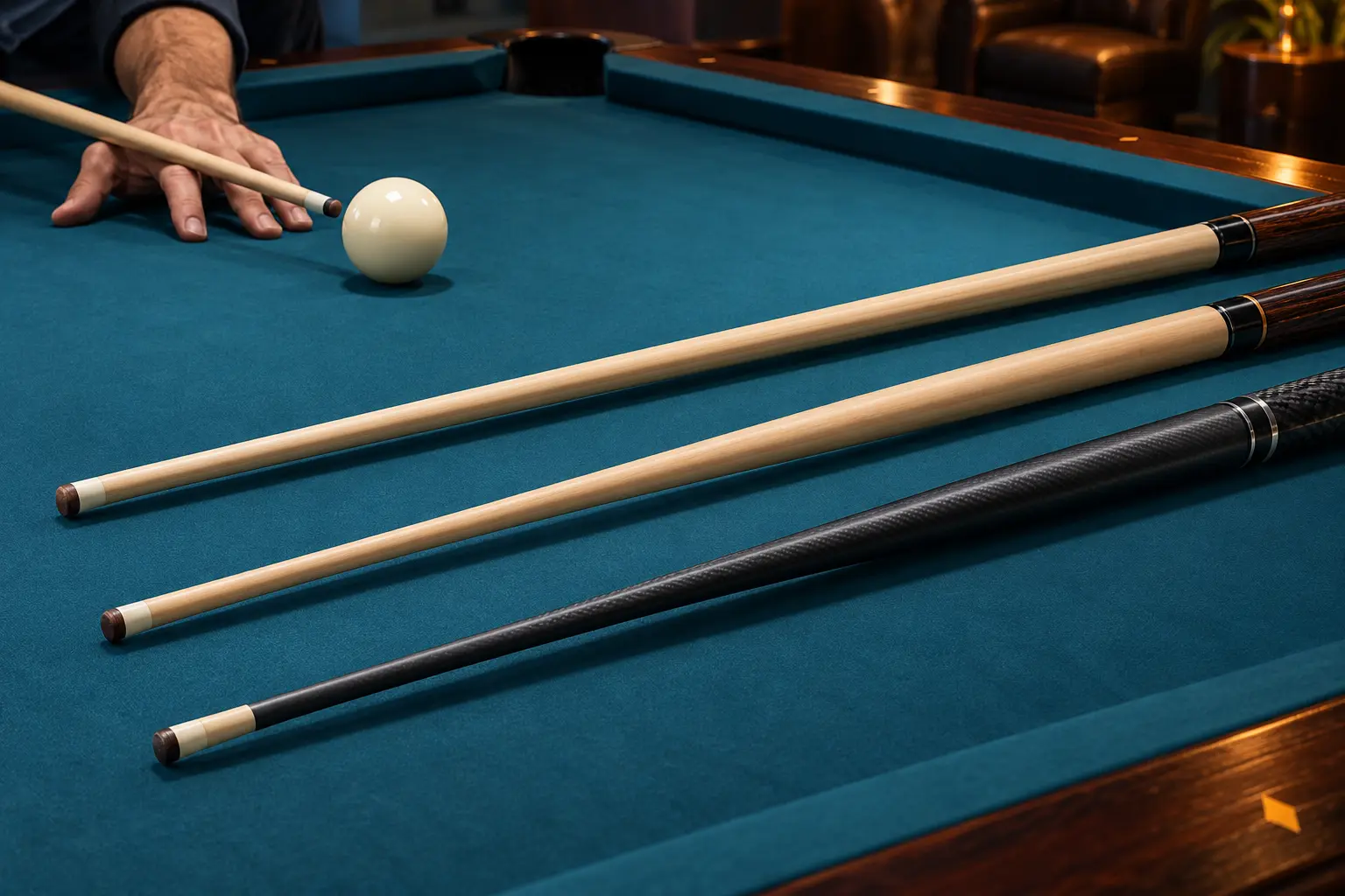
Describe the profile without relying on a family name
A front section that changes very little in diameter is often described as nearly parallel. A profile that widens steadily is commonly described as conical. Many shafts use a blended curve that fits neither description cleanly. Those words describe a general shape, not a shared industry measurement method.
Record the exact shaft identity privately with the cue record, but compare candidates with the same physical stations. Do not transfer a stiffness, low-squirt or accuracy claim from the shape alone; material, wall construction, ferrule, tip, length and front-end mass remain separate variables.
Build a six-station PROFILE map
Mark the stations on low-tack tape beside the shaft, not on its finish. Use a measuring tool that can contact the surface gently and consistently; squeezing a caliper can damage a finish or create a false reading. Take two readings at each station, remove and replace the tool between them, and write the displayed precision without adding invented certainty.
For a simple comparison between two stations, compute diameter rise as (far-station diameter − near-station diameter) ÷ station separation. Example: 12.60 mm at 3 inches and 12.96 mm at 9 inches gives a 0.36 mm change across 6 inches, or 0.06 mm per inch for that interval. This is a local description, not proof of a constant taper or playing quality.
| Station from tip face | Diameter reading 1 | Reading 2 | Difference | Observation |
|---|---|---|---|---|
| 1 in / 25.4 mm | ___ | ___ | ___ | front section |
| 3 in / 76.2 mm | ___ | ___ | ___ | ___ |
| 5 in / 127.0 mm | ___ | ___ | ___ | ___ |
| 7 in / 177.8 mm | ___ | ___ | ___ | typical short bridge |
| 10 in / 254.0 mm | ___ | ___ | ___ | typical medium bridge |
| 13 in / 330.2 mm | ___ | ___ | ___ | long-bridge reference |
Overlay the profile on your BRIDGE range
Measure from the cue-ball side of the bridge hand to the cue-ball address point. Mark the usual and longest comfortable bridge lengths. These distances tell you which part of the diameter map actually passes through the fingers during the stroke.
Use a 0–3 comfort scale: 0 means stop because of pain or unsafe binding; 1 means repeated pinch or forced looseness; 2 means usable with a noticeable change; 3 means clear and repeatable. Do not sand or modify a shaft to make this test pass.
| Bridge | Measured bridge length | Warm-up strokes | Contact or pinch? | Comfort after 10 shots |
|---|---|---|---|---|
| Open bridge | ___ | 5 | yes / no | 0–3 |
| Closed bridge | ___ | 5 | yes / no | 0–3 |
| Rail bridge | ___ | 5 | yes / no | 0–3 |
| Elevated bridge | ___ | 5 | yes / no | 0–3 |
Run the same 30-shot STROKE trial
The score compares your repeatability under defined conditions; it does not isolate taper as the cause. If complete shafts differ in tip, construction or mass, record those confounders instead of crediting every result to the profile.
Repeat on another day when scores are close. A useful selection is the profile that clears your bridge range and supports a repeatable delivery without requiring a hidden compromise.
- Use an illustrative 100×50-inch bed represented by 8×4 units, origin lower-left between cushion noses. Equal 2.25-inch balls have radius 0.09. Hold object O=(6,3), real upper-right corner P=(8,4), tangent cue center G=(5.839003,2.919502), and cue start C=(4.407920,2.203960). These centers are collinear. Scale to actual equipment and remove measuring aids before shooting.
- Take ten comfortable straight pot attempts with a familiar ordinary rolling request, ten controlled stop attempts and ten controlled follow attempts. Only one active pair is on the bed. For stop call a resting-center disk radius 0.20 at G; for follow call the same radius at (6.375659,3.187830), 0.6 units forward from G. The disks are chosen tolerances, not promised outcomes.
- Keep the same bridge length and the same stated delivery request for each matched task and candidate. Calibrate safely before scoring; hold a request that cannot be delivered comfortably rather than forcing spin.
- Record legal called pots separately for each ten-shot task. For stop and follow, record joint pot-plus-disk finishes as a separate count out of ten. In the rolling block, log the arrival request and visible rotation only when observable; do not invent a second outcome point. Do not combine these different tasks into a 60-point ability score.
- Record bridge pinch, hand adjustment, shaft contact and actual struck attempts beside each result. Stop for a loose component, finish damage, discomfort or unsafe clearance.
- The four bridge-readiness rows above are separate support checks. Their five unstruck sliding checks and any optional comfort shots are not silently added to this 30-strike comparison; log that work separately.
Choose a next action from the evidence
| Finding | Next action | Do not conclude |
|---|---|---|
| Profile is comfortable; score repeats | Keep it on the shortlist | The taper caused every result |
| Closed bridge pinches at long length | Retest with normal bridge or another profile | A thinner tip alone will fix it |
| Feel changes but outcomes do not | Decide whether comfort matters enough | One profile is more accurate |
| Outcomes vary by day | Hold the decision and repeat controls | The first session is definitive |
| Joint or shaft condition is uncertain | Resolve compatibility or service first | The taper test is valid |
Compare wood, composite and carbon shafts when construction is the variable you need to test.
Identify a cue joint before replacing a shaft before a profile trial with a replacement shaft.
Sources and further reading
References support the specific factual information above. The practical checklists are Ariakon editorial guidance.