
Cue maintenance · 4 min read
Distinguish Cue Warping From Joint Alignment and Rolling Surface Errors
The first straightness screen tells you what looks different. This comparison worksheet asks whether that observation follows the section, the support or the assembled joint. It cannot certify a centerline or authorize repair. Keep the rotation index, contact points and viewpoint fixed enough to reproduce the evidence, and name a cause only after qualified inspection.
Define two safe observation supports
Use two clean, stable supports that are suitable for the finish and long enough to avoid exposed pins or tips contacting an edge. Record what is known about their flatness; neither an apparently level table nor a household edge is automatically a precision reference. If safe rolling contact cannot be established, use sighting and service inspection instead.
Keep lighting, camera height and the observed physical feature consistent. Use a visible cue feature as the 0° index in photographs; record quarter turns without adding tape or ink to an unfamiliar finish. Record wrap seams, bumper projections, collars and taper before attributing their movement to a bend.
Complete the basic straightness screen before extending it into this controlled comparison.
Fill the twenty-four-cell comparison matrix
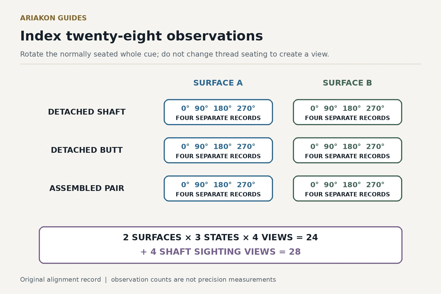
Each slash-separated orientation gets its own record: 2×3×4=24. Rotate the entire normally seated cue; do not reseat its threads at four different tightnesses. The matched pair must already be safe to assemble. Binding, cracks, loose hardware or a visible abnormal gap ends the matrix and goes directly to service.
Add four detached-shaft sighting records under the same diffuse light, using the four orientations: 24+4=28 observations. Repeat any suspect row after lifting and repositioning, and log repetitions separately. The 28-record base is a bookkeeping total, not 28 independent measurements or a statistical confidence claim.
| State | Surface A: 0° / 90° / 180° / 270° | Surface B: 0° / 90° / 180° / 270° |
|---|---|---|
| Detached shaft | Feature, contact points, view and departure ___ | Same records ___ |
| Detached butt | Feature, raised contact and departure ___ | Same records ___ |
| Normally assembled matched pair | Visible joint gap, collar transition and departure ___ | Same records ___ |
Read patterns as leads, not diagnoses
A bowed rotating section need not depart in the same direction at every orientation. A periodic repeatable pattern can be important, but a visible offset does not distinguish a bowed centerline from an off-center tip, collar or support effect. Avoid converting a silhouette into a tolerance verdict.
Model-specific service instructions can require the complete shaft/butt pair. Ask what to send before shipping. No facing, pin bending, heated straightening, hanging-weight treatment, abrasive carbon treatment or trial fitting of an uncertain shaft belongs in this observation protocol.
| Pattern | What remains plausible | Next action |
|---|---|---|
| Departure changes with support or contact points | Surface, taper or raised-feature effect | Repeat after documenting the contact; do not reshape |
| The same shaft feature gives a reproducible pattern across both supports and sighting | Section or front-end geometry deserves fixture inspection | Send indexed photos; ask for centerline/runout assessment |
| Sections look stable, assembled pair appears different | Face, pin, insert, collar or assembly effect | Send the relevant complete pair as requested |
| Butt rises at a wrap seam or bumper | Non-cylindrical contact lifts the section | Use a suitable sight view; do not remove the feature |
| Pattern is inconsistent after repositioning | Method or observation insufficient | Keep cause UNKNOWN |
| Gap, crack, loose pin or binding threads | Unsafe assembly or damage | Stop use and contact qualified service |
Work an incomplete matrix honestly
Hypothetical record: the detached shaft row has eight observations that look stable. The butt row has eight observations that rise at the bumper contact. The assembled row has eight observations with one uncertain gap view. Four additional shaft sighting views look stable. That accounts for all 28: 8+8+8+4=28; it does not make the uncertain gap pass.
Record the support effect as an observed lead and the joint cause as unresolved. If a defect or abnormal opening is visible, stop use. Otherwise ask service to assess the full matched pair rather than ordering a shaft to treat an unconfirmed warp.
Send an eight-field handoff
For Ariakon carbon equipment, the current FAQ supports soft-cloth care and avoiding abrasives, excessive heat and modifications. It does not supply a straightness tolerance or authorize a joint correction. This worksheet keeps that boundary intact.
- Cue and component identities, including later replacements.
- Symptom and when it first appeared.
- Impact, storage or environmental change, if known.
- Support descriptions and flatness limitations.
- Rotation index, contact points and fixed camera view.
- The 24 matrix records plus four sighting views; extra repeats labeled separately.
- Visible joint/section photographs and purchase/service records.
- Exact question, requested inspection and no-home-repair statement.
Preserve the cue before service changes it when the inspection advances to an authorized repair.
Document joint geometry before purchasing a replacement part.
Sources and further reading
References support the specific factual information above. The practical checklists are Ariakon editorial guidance.