
Equipment guides · 4 min read
Should You Use a Low-Squirt Shaft? A Decision and Comparison Worksheet
A shaft label cannot diagnose why a sidespin shot missed. This resource separates the possible effects, records a short near-launch comparison, and makes a conservative equipment decision. It is not a promise that lower squirt always wins, a proprietary aiming correction or a long-range swerve-cancellation drill.
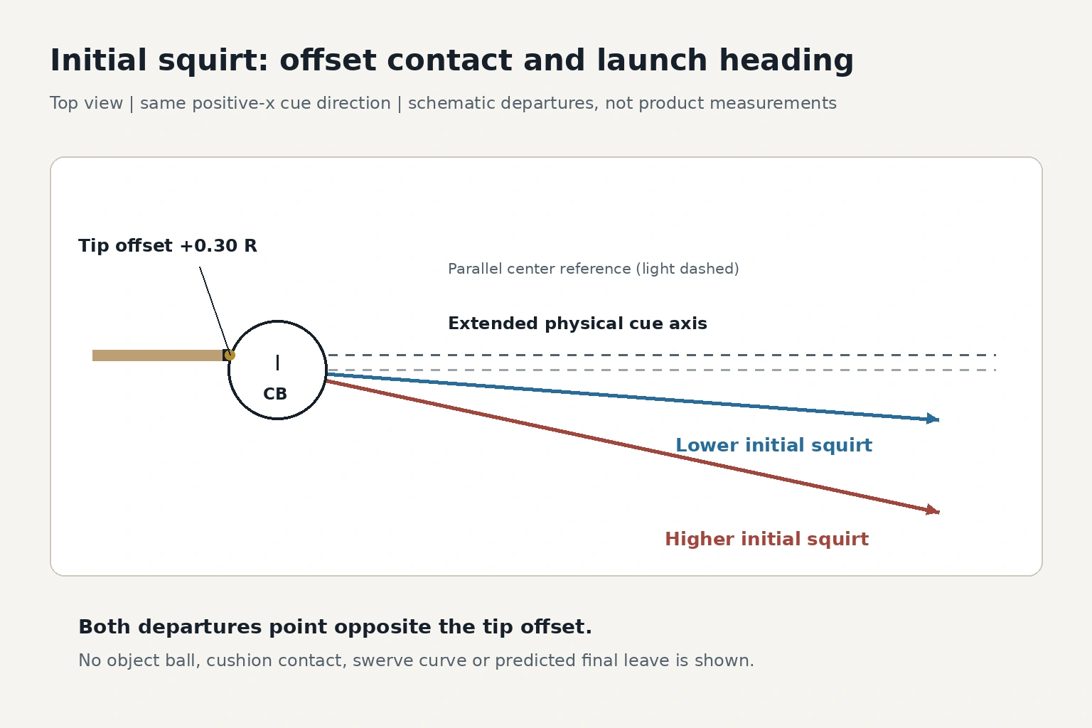
Identify which effect the question concerns
A tip contact to one side can launch the cue-ball center to the opposite side of the cue direction. The extended physical cue axis passes through the offset contact, while the parallel reference through the ball center provides a heading comparison. Do not measure departure from the offset axis as though it began at the ball center.
Collision research models cue-end structure as one influence on the response. It does not establish a ranking of current products or a universal numeric squirt angle. Total cue mass, a material name or a marketing label alone cannot predict your assembled cue’s response.
| Effect | Where it occurs | What this comparison can say |
|---|---|---|
| Squirt | Initial cue-ball departure during offset tip impact | Near-launch heading relative to cue direction |
| Swerve | Later cue-ball curve on the cloth | A distant finish is not pure squirt evidence |
| Throw | Object-ball direction changes in ball contact | No object ball is used in the near-launch comparison |
Freeze the equipment and observation contract
Use an illustrative 100×50-inch bed represented by x=0 to 8, y=0 to 4, measured between cushion noses from the lower-left corner. Equal 2.25-inch balls have radius 0.09 and diameter 0.18 units. Intact-cushion center bounds are x=0.09 or 7.91 and y=0.09 or 3.91. Real pockets interrupt those boundaries at the corners and side midpoints (4, 0),(4, 4). Scale to your measured bed and ball size; actual jaws and shelf require inspection. Coordinates are ball centers, not edges or universal diamond values.
The offsets are 0.30×0.09=0.027 units, about 0.3375 inch in this illustration, measured from the cue-ball center at address in the top view. They are not a claim about the maximum safe offset or a prescription for every tip. Use only a controlled contact that avoids miscues; reduce or hold the request when uncertain. Do not place hard gates or chalk cubes on the cloth.
A shaft that does not mate safely cannot be compared on the same butt. If the whole cue changes, describe a whole-cue comparison. A phone view that cannot resolve contact and heading leaves those rows unknown rather than producing a numerical shaft ranking.
| Field | Required record |
|---|---|
| Assembly | Exact shaft, tip, butt and compatible joint; no forced mating |
| Geometry | Cue center (2, 2); direction parallel to positive x |
| Tip requests | Center; lateral offsets +0.027 and−0.027 units |
| Elevation and pace | Same comfortable near-level address and calibrated moderate pace |
| Camera | Stable permitted overhead view, outside every ball and player path |
| Measured interval | Cue-center crossing from x=2.2 to x=2.7, before any collision |
| Confounds | Tip, mass, balance or butt changes explicitly noted |
Check joint identity before combining parts when compatibility is unresolved.
Inspect the shaft’s bridge and stroke fit before blaming delivery changes on squirt.
Measure the early heading, not the final resting offset
First take two declared unscored calibration strikes per candidate. Then record four strikes for each of the three tip requests per candidate: 2×3×4=24 scored strikes, 12 per candidate, plus 4 calibration strikes=28 total. Alternate candidate order by request and reverse it on a separate repeat occasion. Stop and use actual denominators if input stability fails.
From the registered view, note the cue-center y coordinates at x=2.2 and x=2.7. The observed heading is atan((y₂−y₁)/0.5), compared with the positive-x cue direction. A hypothetical y change of−0.005 gives atan(−0.01), approximately−0.573 degrees. This is a geometry example, not a measured shaft result.
The interval may still contain early curve, camera error and delivery variation. Record heading only when both crossings and the frozen contact are visible; otherwise mark unresolved. A center-contact baseline that drifts or varies greatly makes an offset comparison inconclusive. Do not infer pure squirt from a long rail return or a pocket miss.
Choose the decision before adding a compensation method
Keep pocketing ability, comfort, contact adherence and the near-launch observation in separate fields. Lower observed departure may reduce one adjustment, but a poorly fitting shaft or unstable contact can outweigh it. Do not calculate end mass from this field test or claim that a small sample predicts accuracy.
Three dispositions are useful: keep the familiar shaft when the actual problem is elsewhere; consider a candidate when it is compatible and repeatably manageable; hold the decision when the measurement or delivery is unresolved. A new shaft also changes the learned reference, so practice adaptation before using it in competition.
Study sidespin effects separately when squirt, curve and throw are being conflated.
Use a separate adaptation guide after deciding to change rather than during this selection test.
Read current Ariakon playing-cue information without assuming this worksheet proves a product-performance advantage.
Sources and further reading
References support the specific factual information above. The practical checklists are Ariakon editorial guidance.